What Is BIM and Why Use It?
The International Organization for Standardization (ISO) defines BIM as “use of a shared digital representation of a built asset to facilitate design, construction, and operation processes to form a reliable basis for decisions.” The National Institute of Building Sciences (NIBS) emphasizes the efficiencies BIM brings to users: “Effective use of BIM has the potential to eliminate enormous waste in the industry resulting from the re-collection and re-creation of project information and data.” BIM is all about data and turning modeled geometry into what sometimes is described as ‘a single source of truth’. This single source ends up containing all relevant model elements and data that impact your portion of the project. Instead of looking at BIM as a specific software solution, approach it as a framework for producing and collaborating on a project. This frees you up to use whatever software you require - it doesn’t matter what your collaborators are using as long as the BIM structure is set up with well-defined deliverables and clear directions for communication and data exchange. A fundamental benefit of BIM is that documentation comes directly from the model. Schedules, reports, and worksheets are all linked to the geometry so that when you make a change in the model, it reflects in the documentation. As in any project, it is imperative to take into consideration the views, insights and opinions from all involved parties - from your own design team to external contractor and consultants - and to have a system in place to handle all of this information, while at the same time incorporate jurisdictional regulations and environmental context.Get your FREE 30-day trial of Vectorworks Landmark.
BIM will also help involve clients and other stakeholders early in the process, thereby avoiding late revisions and time-consuming edits. Your 3D model is much easier to interpret by non-specialists than traditional 2D plans, which means all parties can engage with your ideas before construction, saving everyone time and money.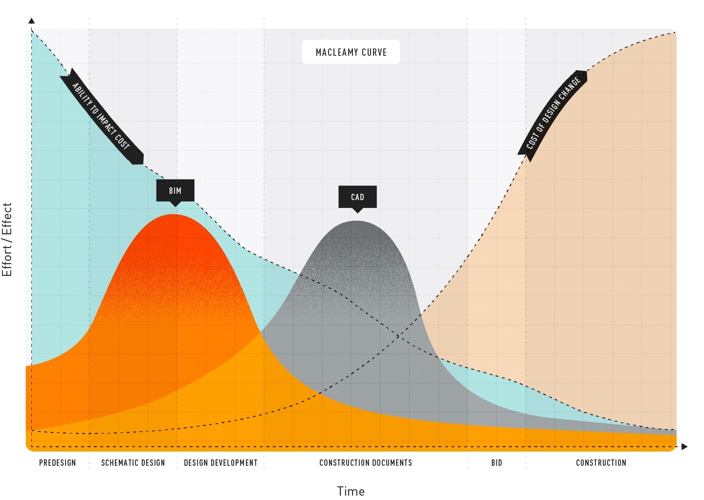 Based on the McCleamy Curve, which illustrates the advantages of using BIM in the design process.
| Phase 1: Pre-design |
| Phase 2: Schematic Design |
| Phase 3: Design Development |
| Phase 4: Construction Documentation |
Phase 1: Pre-design
Whether using BIM or not, we recognize that there’s a lot of work to do before you actually start designing. This section is all about that pre-design phase.The BIM Implementation Plan (BIP)
To ensure your firm is ready for your initial BIM project, your first step should be putting together a BIM Implementation Plan (BIP). This is your firm’s personalized plan to get up to speed and to implement the new framework. Starting off with reviewing your current workflow, you’ll then move on to formalizing your BIM goals and what BIM means to your organization, plan how to implement new skills and define key BIM positions within your organization. This is a step on your BIM journey that can be tempting to overlook, but which will help you stay on track through the project. The document below is is our guide to assembling a BIP. START PLANNINGDeveloping a Program
You’re used to develop a project program — this is nothing new. However, in a BIM project there is one document which will steer all of your planning — the BIM Execution Plan, or BEP. The BEP is the responsibility of the lead appointed party (the body responsible for coordinating information between the delivery team and the appointing party). It will be the roadmap for everyone involved in the project and show that the team can manage project information in line with any information requirements provided to them (the information delivery strategy). It will also state what software, hardware, and IT infrastructure to be used, and name persons responsible for the information management function. Even if it’s the lead-appointed party issuing the BEP, it should be created based on a dialogue between all parties involved. Don’t feel intimidated — question its content and ask for things not covered within. The BEP can be an evolving document — often both a pre- and a post- contract BEP are produced. Once you and your collaborators confirm initial and subsequent dependencies and the expected deliverables, it’s time to start thinking about designing the project itself.Taking Site Inventory
As always, developing a program includes site visits to collect data. This — together with professional surveys of land and trees, GIS maps, environmental and ecological data — will be the base for the Landscape/Townscape Character Assessment and further for your design decisions. Outside the traditional survey formats — such as DWGs, PDFs and Shapefiles — you can also include processes like Photogrammetry (Photos to 3D Models in Vectorworks), which can be used via Vectorworks Cloud Services to generate point clouds and mesh surfaces that represent inventoried elements of the site. Drone imagery can also be included, both for visualizations and for data collection. A BIM project is based on the same data collection — however, it’s imperative to ensure all parties’ drawings and models are geographically aligned, so when the BIM manager creates the federated model for clash detection, it all fits together. To help with this, use Landmark’s GIS function — a system which aligns georeferenced positions (latitude and longitude) with cartesian coordinates (x and y). It also includes a built-in link to Esri, giving you access to both satellite imagery and street maps of the whole world. Vectorworks Landmark can also direct-import tree surveys from arborists. This usually comes in spreadsheet form and Landmark makes it easy to transfer this to your site model in both 2D and 3D, while maintaining all the individual tree data and geometry.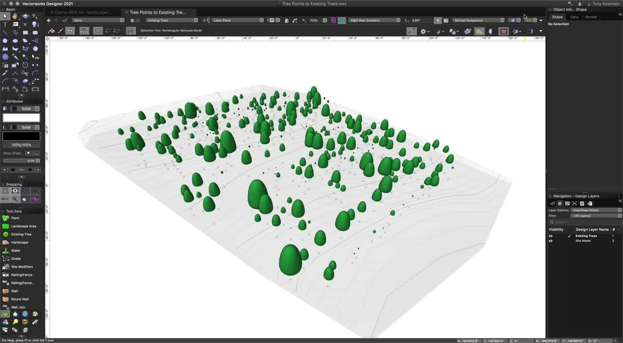
Learning from Site Analysis
After inventory comes analysis, a defining aspect of any design process. There’s a lot that goes into it, and you’ll find as you continue with BIM that this is not just a one-time thing. Constantly evaluating your project, specifically how it lines up with the client’s vision, is key. Vectorworks Landmark comes loaded with a wide range of analysis tools. Consider the Heliodon, which allows you to run sun and shade studies and animated simulations. See what it looks like: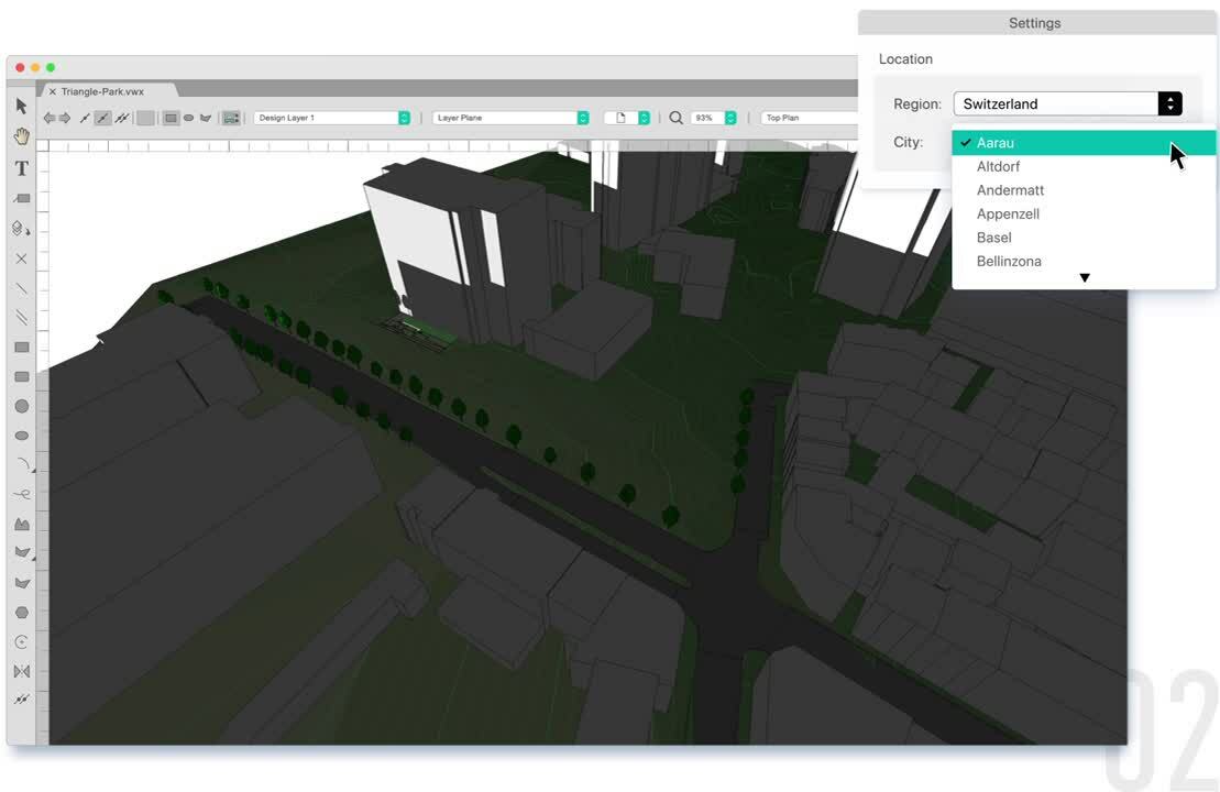
 A site model showing colorized slope contours.
Phase 2: Schematic Design
In this section, we’ll concentrate on how to integrate the findings from the initial analysis into your schematic design and how this fits into a BIM workflow.Forming a Concept Design
Schematic design comes down to visualizing spatial relationships, which you can do with basic 2D drafting tools like the Polyline, Rectangle, Circle, and Arc tools. Once these spaces are defined, you can convert them to un-styled hybrid objects like walls, hardscapes, or landscape areas for 3-dimensional depth. We will dive deeper into these in just a bit. The advantage of Vectorworks in basic 2D drafting comes from the ability to edit 2D and hybrid surfaces with commands like Add Surface, Clip Surface, Intersect Surface, and Combine Into Surface, which enable an iterative workflow. When it comes to Level of Development (LOD), recently renamed Level of Information Need in the UK, the schematic design phase is LOD 100 and getting into LOD 200. Here’s an approximation of detail levels for each LOD: Level of Detail (or Level of Information Need) shown through curb objects.
Three Tools to Master
Many schematic design conventions relate to basic tool use, but there are three tools in particular to call out that are instrumental in preparing your model for LOD 300 and further project development.Hardscape Objects
Use these to identify areas where you want paths, walkways, sports courts, parking lots, or other hardscapes. For now, it’s just a visual to signify intent. Later you can either style the hardscape with materials or opt to replace your object with a pre-styled hardscape from your Resource Manager. You could signify hardscape areas with simple geometry but using the dedicated Hardscape objects facilitates data-rich smart objects down the road, which vastly streamlines documentation.The Landscape Area Tool
As we move into softscapes, our second tool is the Landscape Area tool. Though Landmark is flexible enough for any shaped object to be used to delineate site areas, the Landscape Area tool is purpose-built for depicting mass planting areas, planting groups, and plant bedlines. You might use the Landscape Area tool to represent mixed plantings of shrubs, perennials or groundcover, or to represent a meadow. Or you might use this tool to define bedline components like mulch, amended soil, drainage gravel, etc. The tool works with the site model to provide measurement of true surface area, not just the projected area — if the area is sloped, the tool will provide an accurate area of the slope’s surface.The Plant Tool
In each of the design phases, you will certainly be evolving your plant recommendations, and through each phase, you will transition from proposing plant type and purpose (i.e. shade, buffer or groundcover) to specifying species, their scheduled size and maintenance instructions. The Plant tool can represent everything from understory mass-planting to individual trees — start with illustrative non-species-specific plant styles in your concept design and use the Replace plant style shortcut to upgrade them to clean, species-specific plant styles, ready for construction document planting plans. Generic plant symbols shown in Landmark's Resource Manager.
Collaboration with Your Team and Consultants
The BIM process depends heavily on collaboration between architects, landscape architects, engineers and other consultants, and this means each firm participating must be prepared for back-and-forth file sharing, addressing each iteration from schematic design and beyond. Landmark supports importing and exporting of DWG, IFC, RVT and various 3D formats, as well as referencing DWG, IFC and PDF files. Click here to see supported import formats and here for export formats. Vectorworks Landmark is ready to pick up a project no matter where it was started. Even if you began the project with a pencil sketch on paper or digital sketch on a tablet or other device, it’s easy to import an image or PDF and design over top of it with proper scaling. For your internal team, Vectorworks Cloud Services is a convenient method for file sharing and storage. You’ll have access to all your files on any web-enabled device. Use the Nomad app in addition to share PDFs, interactive 3D models, and panoramic images with clients and collaborators on the go. An added benefit of Cloud Services is that you can delegate resource-heavy activities (renderings and animation movies, for example) to the cloud so you can continue design work on your computer.Presentations to Visualize Your Ideas
Quite often the project you’re working on during the concept or schematic stage might be just that — a concept. Clients and stakeholders are looking for the design professional’s expertise for a solution to their problem or program, and one of the best ways to relay your solutions is to share high-quality graphics which will help them connect with the look and feel of the project. Vectorworks Landmark can create detailed, immersive presentations that bring the client’s vision to life. Even though this isn’t strictly information modeling — BIM is about shapes, volumes, spatial relationships, and attached data, not necessarily aesthetics — it’s still a relevant aspect of BIM framework. Your model will be the underlying structure — that singular source of truth — and by adding visual attributes to it, your design comes to life. You can then render it with Vectorworks Renderworks, and even add post-production styles in Vectorworks Cloud Services. On your printable sheet layers, viewports can show section views of your model. These viewports are perfect for conducting whole site or vignette sections during spatial relationship and height studies. Mark these sheet layer viewports with data tags and annotations to communicate necessary data like dimensions. To accompany a 3D model, you might consider a walkthrough animation or an immersive cloud presentation.Materials, Quantities, Measurements, and More
During this conceptual phase, you will have a pretty good idea of what general materials, characteristics, and plants you want for the site, but nothing final — the first proposal for materials and plants, like most of the schematic design phase, is heavily open to revision by the client.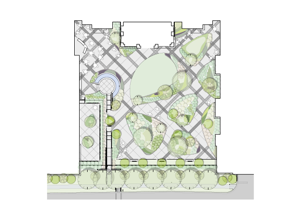 Conceptual site design courtesy of Surface 678.
Phase 3: Design Development
You’ve shared schematics with the client, and they’re ready to see your ideas fleshed out — now, to incorporate revisions and specifications necessary to finalize the design, you can rely on much of the work you’ve done already. In addition to the setup in prior phases, there are a number of capabilities in Vectorworks to note as you advance through design development.Maturing the Project & Refining Early Design Decisions
If schematic design is about an overall master plan and program, design development is drilling into each individual space and element to create a package that’s viable, on budget, and meets regulations. A crucial aspect of design development is verifying that site elements fit within overall constraints. These constraints can include area, parking requirements, local codes and ordinances (including tree preservation and water efficiency), ADA accessibility, and budget, among others. Data visualization is invaluable here. You can think of data visualization, in part, as a spell-checker — by applying graphics to certain data, you’re better able to see the impacts of that data so you can design with this in mind. In her webinar on Vectorworks University, Anne Arbetter of Futurity, Inc. shares how she visualizes different characteristics of existing trees. By color-coding the trees’ conditions (poor, good, etc.), she’s better set up to develop a tree preservation plan for the site. Data visualization showing whether existing trees are suitable for dry, normal, or moist situations.
Coordinating the BIM Model with Consultants
Design development is where a majority of file collaboration occurs in a project’s lifecycle. Here we’ll discuss some of the workflows you can use within Vectorworks to support your BIM collaboration. First, if your firm has multiple team members working remotely, or from distant branch locations, your separated team members can stay productive through Vectorworks’ multi-user environment called Project Sharing. This also enables multiple team members to work on the same project model at the same time for a more holistic approach to project management. As the “one model” approach is a big part of a BIM workflow, this becomes a powerful addition to your BIM tool portfolio. Next, importing files from consultants. Get your FREE 30-day trial of Vectorworks Landmark. The ability to reference DWG drawings is a standard way of working and will keep your model space free from contamination. This also means that you have access to the most up-to-date background data with a simple “update” click. Say you’re working with a civil engineer who previously has provided plans for stormwater drainage, and which now have been updated — instead of reimporting the DWG, you simply update the reference. This will ensure that you’re not wasting time and resources based on old parameters. This concept is also hugely important in a BIM environment, where your model will be combined with other parties’, and you want to present an IFC file containing only your own work.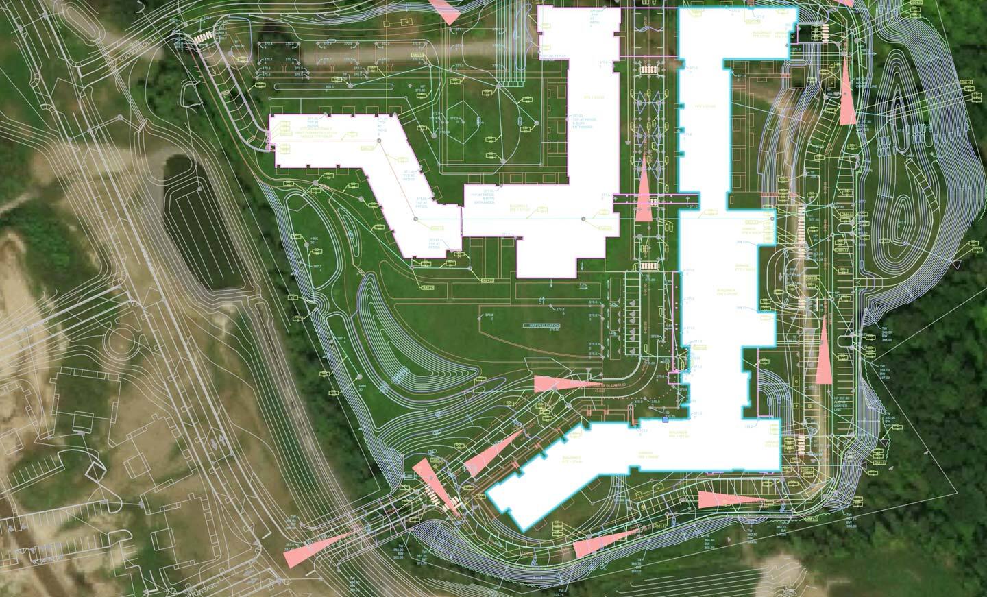
Collaboration within Landmark includes existing geoimagery, civil engineer base plans, as well as proposed architect’s models. Project files courtesy of Crowley Cottrell, LLC.
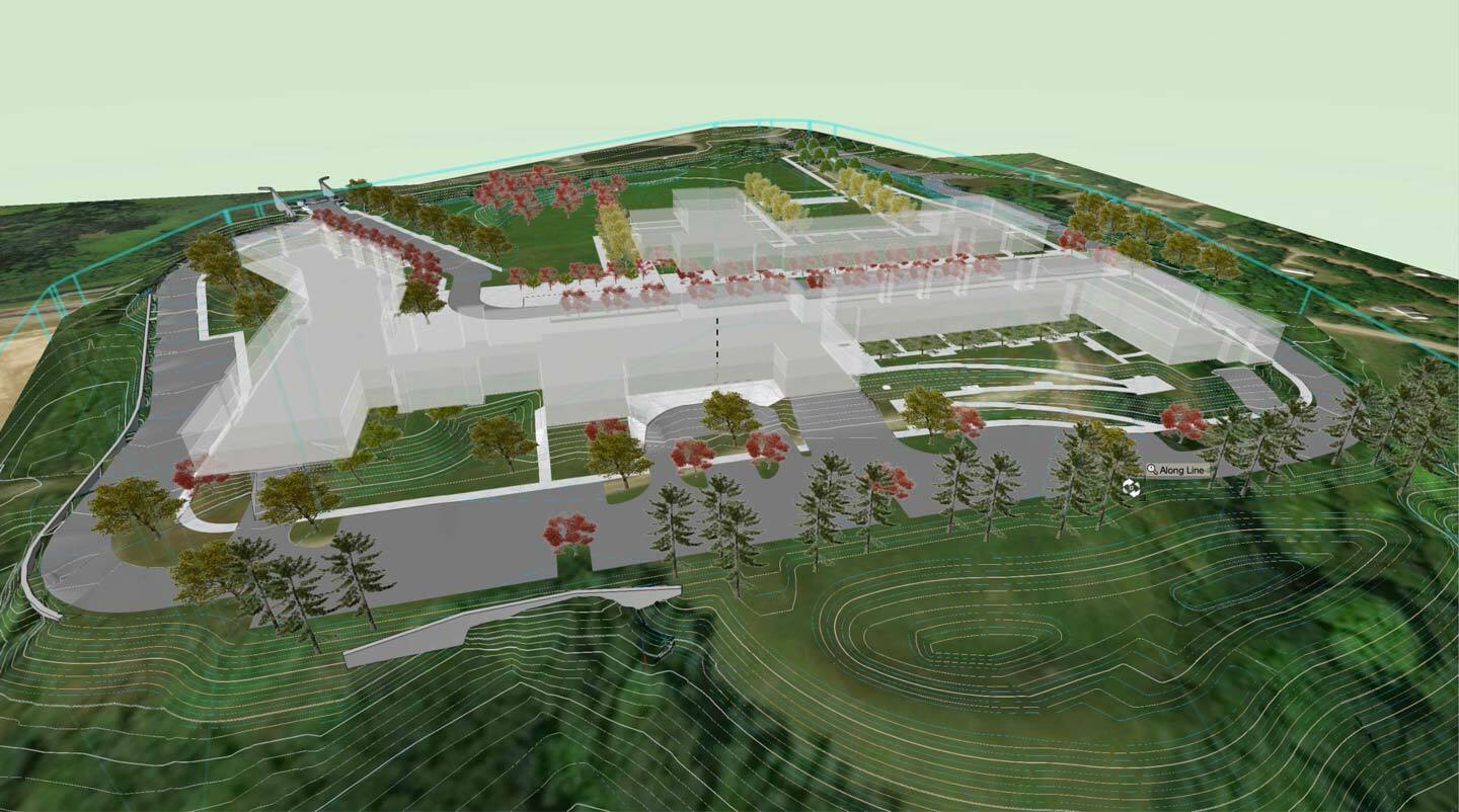
Transformation to 3D landscape model includes terrain (Site Model), parking and drive (Hardscapes), and building (Massing Model) with proposed planting as the project develops. Project files courtesy of Crowley Cottrell, LLC.
The collaboration goes both ways — you need to be able to import the work of collaborators in the same way as they need yours. Let’s get into some specifics about sharing work done with Vectorworks Landmark. Globally, the AEC and adjacent industries have responded to the increased need for multiple disciplines to exchange their portion of the project by using a non-proprietary BIM format called Industry Foundation Classes (IFC). You will appreciate knowing that Vectorworks has been importing and exporting IFC files from just about its start. In fact, all of the smart objects within Vectorworks come with IFC tags, enabling worry-free exchanges with other IFC-based disciplines. If you create an object yourself and need an IFC exchange, you’re able to create and assign custom IFC property sets (pSets) that will work in model-checking software. Read more about Vectorworks’ IFC4 certification. This is a good time to introduce the Data Manager. The Data Manager is Vectorworks’ hub for mapping and controlling data assignments. As mentioned, smart objects will automatically have IFC assignments — however, sometimes your BEP has specific requirements for how the IFC exchange should be structured. In the Data Manager you can edit and add IFC data sets and map data from attached records or Vectorworks native data sets. You can also set up data sheets — personalized sets of data, visible and accessible in the Object Info palette in your workspace. This can be incredible useful to guide the design team to what data is required at the different stages of a project and reflect the LOD needed at each phase. By only displaying the data field needed for the active design phase, you remove the “how much data is enough?” question. Vectorworks comes with a large set of pre-formatted worksheets for everything from Plant specification to Material data, and you can create your own through the Create Report command. For your BIM project there are some specific reports that show objects with IFC entities. These preflight sheets are useful when preparing your model for IFC export. From Vectorworks 2021 you can also export and import Excel spreadsheets directly to/from Landmark. Below is an example of a detailed plant schedule.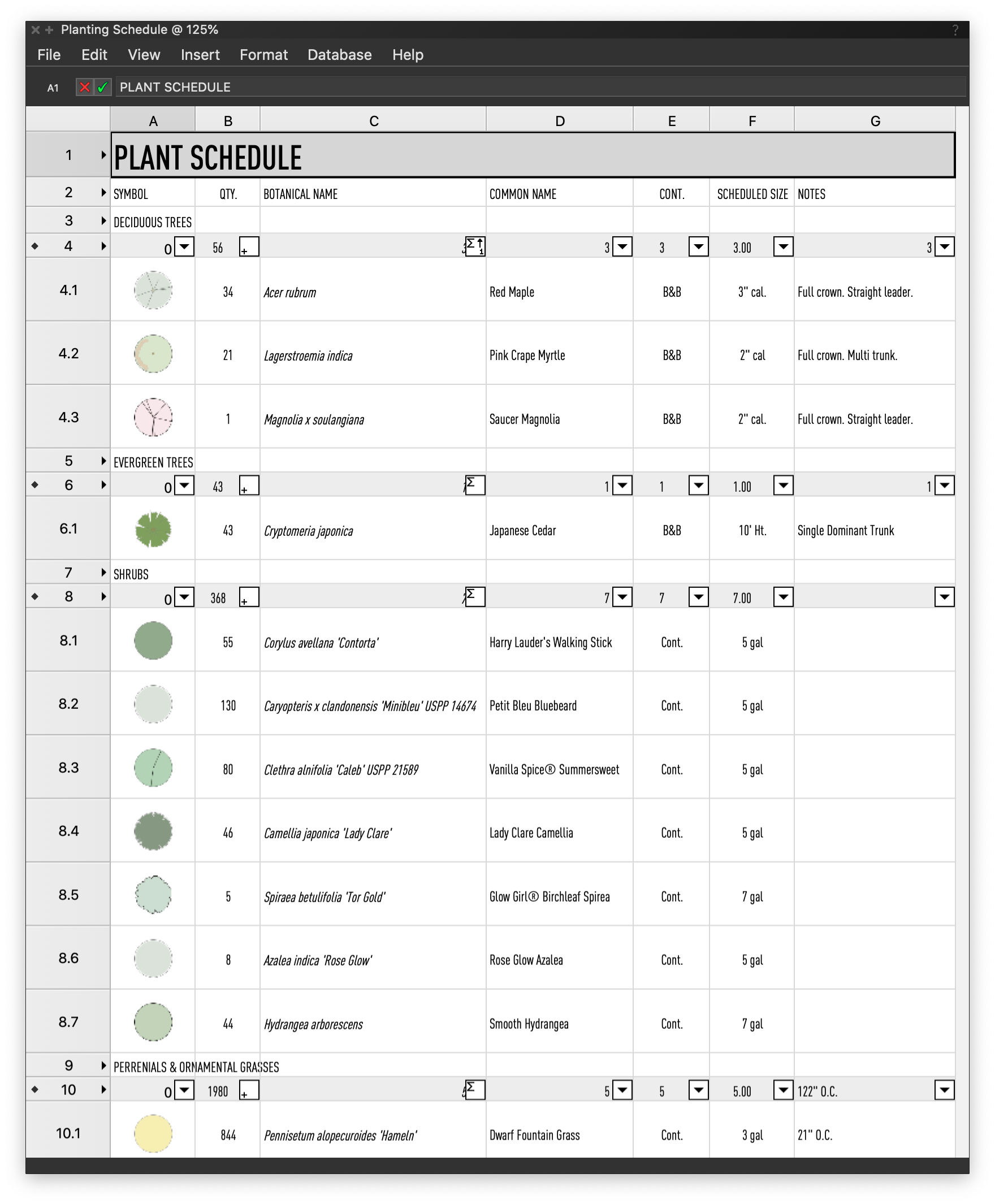 Plant schedule created with Vectorworks' built-in worksheets.
- Collaborative Design Tools for Landscape Architects
- Strategies for Adopting BIM in Landscape Architecture
- Moving to BIM for Landscape: What You Need to Know
- 3D Modeling for Landscape Analysis
- The World According to BIM
- Open BIM and IFC for Landscape Architecture
- Enhance Site File Collaboration with Georeferencing
- Productive Remote Work Through BIM for Landscape
- Transitioning to Information Modeling Workflows
- Water Conservation with the Future In Mind
- Augmenting Landscape Architects’ Design Workflows with Information Modeling
- Water Efficient Landscape Design
- Advanced Site Modeling
- Pacific Coast Land Design (PCLD)
- Maffei Landscape Design
- Landscape Architecture Bureau (LAB)
- scape Landschaftsarchitekten
- PWP Landscape Architecture
- Holcombe Norton Partners, Inc.
- McGregor Coxall
- Transitioning to BIM for Landscape with Vectorworks Landmark
- Strategic Planning Guide for Adopting BIM for Landscape Architecture in Vectorworks Landmark
- BIM Interoperability for Landscape Architecture: IFC Exchanges in Vectorworks Landmark
- A Guide to Data Visualization with Vectorworks
- Introduction to Irrigation Design & Water-efficient Landscape Design
- Strategic Planning Guide for Adopting BIM for Landscape Architecture in Vectorworks Landmark
Phase 4: Construction Documents
Arguably the most important phase of the BIM process, construction documentation is about compiling the design deliverables needed to implement the site design. Much of the groundwork is already there — if you’ve followed the BEPs structure of deliverables, you should have sufficient data spread through smart objects, tagged geometry, and worksheet reports. Implementing landscape-specific BIM workflows with smart coordination between the model and worksheets is hugely beneficial to producing construction documents. The time and resource savings are tremendous.How to Create Construction Documents in Vectorworks Landmark
As we advance into LOD 350 and 400, take note of a few dynamic features that make Vectorworks Landmark the premier BIM solution for landscapes. Even if BIM is based in the 3D model, there’s still the need to produce detailed drawings. In Vectorworks, similar to using paper space layouts, Sheet Layers are where you compile information for these construction documents. You can create viewports of the entire model, as well as cropped views, with specified layer and class visibility settings, projection, render mode, and orientation parameters. The viewports have a specific annotation mode for adding annotations, dimensions, and additional details to the model views.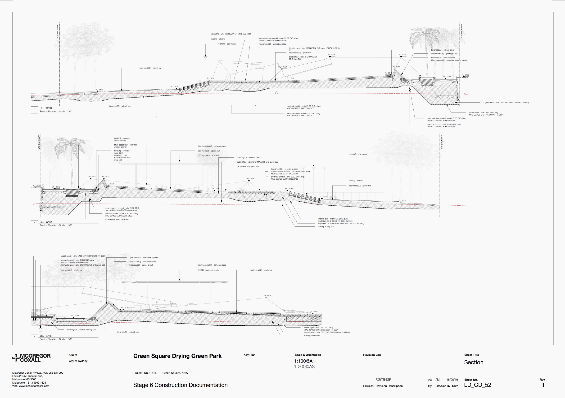
Multiple viewports on a sheet layer showing construction details. Image courtesy of McGregor Coxall.
The Title Block tool is used to add the unique identification of a file (termed “information container”) to your Sheet Layers, as well as to revisions and issue data. Being fully customizable, it gives you control of the final look of your drawings. It also means that you can set up your Title Block to accommodate any national requirements on naming conventions, or requirements set out in the BIM Execution Plan (BEP). Like so many other documentation features, Title Blocks are smart in that they’re linked to drawings and record formats. Smart Markers is another time saving tool. They streamline the workflow by linking Sheet Layers to their corresponding location in the model, or to other Sheet Layers for further detail. Essentially smart stickers, these markers can be represented by your preferred naming system and firm graphic standards to be used for coordination on a variety of things like sections, elevations, references, and details. The typical workflow for creating these Smart Markers is to introduce them to the Annotations window mentioned above. The bi-directional updating capabilities of Smart Markers make iterations painless — make a change to the viewport and the marker updates as well, so you don’t have to spend time manually updating and coordinating information. And, when you publish PDF documents, Smart Markers automatically create hyperlinks to streamline navigation through potentially dozens of pages of construction plans.